Multi-focal Plane Microscopy
Introduction
Fluorescence microscopy of live cells represents a major tool in the study of trafficking events. The current microscope design is well adapted to imaging fast cellular dynamics in two dimensions, i.e., in the plane of focus. However, cells are three dimensional objects and intracellular trafficking pathways are typically not constrained to one focal plane. If the dynamics are not constrained to one focal plane, the currently available technology is inadequate for detailed studies of fast intracellular dynamics in three dimensions. Classical approaches based on changing the focal plane are often not effective in such situations since the focusing devices are relatively slow in comparison to many of the intracellular dynamics. In addition, the focal plane may frequently be at the “wrong place at the wrong time”, thereby missing important aspects of the dynamic events.
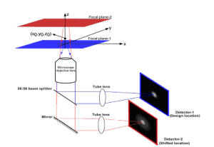
We have developed an imaging modality, multifocal plane microscopy (MUM), to allow for 3D sub-cellular trafficking studies within a live cell environment [1,2]. In MUM, the sample is simultaneously imaged at distinct focal planes (Fig. 1), which enables the visualization of intracellular events that occur at different focal planes [1,3,6].
A key aspect of quantitative tracking of single molecules in three dimensions is that the position of the single molecule has to be determined with high accuracy. The identical problem arises in 3D super-resolution approaches, such as PALM, STORM, FPALM, dSTORM etc., where also the 3D location of a single molecule needs to be estimated with the best possible accuracy. Here an important aspect of MUM arises in that it overcomes a severe problem of 3D estimation in conventional microscopy, i.e. the depth discrimination problem (see below). This is in addition to MUM being able to image samples over a larger depth in three dimensions than conventional microscopy can do.

Figure 1. The figure shows the principle and schematic of a multifocal focal plane microscope. The figure illustrates the effect of changing the position of the detector relative to the tube lens, which results in imaging a plane that is distinct from the plane that is imaged by the detector positioned at the design location.
Principles behind MUM
Fig. 1 shows a schematic illustrating the principle behind MU
M. The light collected from the sample by an infinity-corrected objective lens is split into two paths. In each path the split light is focused onto a detector which is placed at a specific calibrated distance from the tube lens. In this way, each detector images a distinct plane within the sample. The MUM setup shown in Fig. 1 is capable of imaging two distinct planes within the sample. The setup can be modified to image more than two planes by further splitting the light in each light path and focusing it onto detectors placed at specific calibrated distances. Presently, we have implemented a MUM setup that can image up to four distinct planes, the details of which are given below.
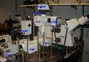
Figure 2. The photograph shows an implementation of a MUM setup on a Zeiss Axiovert 200 microscope. The setup is configured to simultaneously image four distinct planes within the specimen. VA1-VA3 – Zeiss video adaptors, CAM1-CAM4: CCD cameras, CC – C-mount/spacer and custom camera coupler assembly.
Implementation of MUM
MUM can be implemented in any standard optical microscope. Here, we provide the details of the implementation in a Zeiss microscope (see Fig. 2); for additional details, please see [1,3,6]. A Zeiss dual-video adaptor (Part # 1058640000) was first attached to the side port of a Zeiss Axiovert 200 microscope. Two Zeiss dual-video adaptors were then concatenated by attaching each of them to the output ports of the first Zeiss video adaptor. To each of the concatenated video adaptor, a high resolution CCD camera is attached by using C-mount/spacer rings and a custom-machined camera coupling adaptor. The spacing between the output port of the video adaptor and the camera is different for each camera, which results in the cameras imaging distinct focal planes.
We would like to note that there are many ways to implement MUM. We have found that the above implementation offers several advantages such as flexibility, ease of installation and maintenance, and adjustability for different configurations. Specifically, the above implementation has the advantage that it can be implemented with essentially off the shelf components and standard filters and dichroics can be used in the Zeiss dual-video adapter. For a number of applications it is important to be able to acquire images in different colors at different exposure times. For example to visualize exocytosis in TIRF very fast acquisition is necessary. However, to image a fluorescently labeled stationary organelle in the cell, low excitation is necessary to avoid photobleaching and as a result the acquisition has to be relatively slow; see [1,3]. In this regard, the above implementation offers great flexibility, since different cameras can be used to acquire images in different channels.
3D super-resolution imaging and single molecule tracking in MUM – improved depth discrimination
Modern microscopy techniques have generated significant interest in studying cellular processes at the single molecule level. Single molecule experiments overcome averaging effects and therefore provide information that is not accessible using conventional bulk studies. However, the 3D localization and tracking of single molecules poses several challenges. In addition to whether or not images of the single molecule can be captured while it undergoes potentially highly complex 3D dynamics, the question arises whether or not the 3D location of the single molecule can be determined and how accurately this can be done.
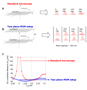
A major obstacle to high accuracy 3D location estimation is the poor depth discrimination of a standard microscope [4]. Even with a high numerical aperture objective, the image of a point source in a conventional microscope does not change appreciably if the point source is moved several hundred nanometers from its focus position (Fig. 3a). This makes it extraordinarily difficult to determine the axial, i.e., z position, of the point source with a conventional microscope.
More generally, quantitative single molecule microscopy for 3D samples poses the identical problem whether the application is localizationtracking or super-resolution imaging such as PALM, STORM, FPALM, dSTORM for 3D applications, i.e. the determination of the location of a single molecule in three dimensions. Here MUM offers several advantages [4-6,10]. In MUM, images of the point source are simultaneously acquired at different focus levels. These images give additional information that can be used to constrain the z position of the point source (Fig. 3b). This constraining information largely overcomes the depth discrimination problem near the focus [5, 6].

Figure 3. Comparison of conventional microscopy and MUM.
Fig. 3c shows the 3D localization measure of z0 for a conventional microscope and for a two plane MUM setup with a focal plane spacing of 500 nm. The 3D localization measure provides a quantitative measure of how accurately the location of the point source can be determined (see Refs. 4-6 for details). A small numerical value of the 3D localization measure implies very high accuracy in determining the location, while a large numerical value of the 3D localization measure implies very poor accuracy in determining the location. For a conventional microscope when the point source is close to the plane of focus, e.g., z0 <= 250 nm, the 3D localization measure predicts very poor accuracy in estimating the z position. For example, for z0 = 250 nm, the 3D localization measure predicts an accuracy of 31.79 nm and for z0 = 5 nm, the 3D localization measure predicts an accuracy of at least 150 nm, when 2000 photons are collected from the point source. Thus, in a conventional microscope, it is problematic to carry out 3D tracking when the point source is close to the plane of focus.
On the other hand, for a two plane MUM setup the 3D localization measure predicts consistently better accuracy than a conventional microscope for a range of z-values, especially when the point source is close to the plane of focus. For example, for z-values in the range of 0-250 nm, the 3D localization measure of z0 predicts an accuracy of 20-25nm in determining the z position when 1000 photons are collected from the point source at each focal plane. An immediate implication of this result is that the z-location of the point source can be determined with relatively the same level of accuracy for a range of z-values, which is favorable for 3D single molecule tracking [5,6].
3D resolution and MUM
The resolution of an optical system is a measure of the system’s ability to distinguish two closely spaced point sources. Classical resolution criteria such as the Rayleigh’s criterion, although extensively used, are well known to be based on heuristic that are not well suited for modern imaging approaches. Recently, we introduced an information theoretic resolution measure for 3D optical microscopy [7-9]. Using this, we have quantified the resolving power of MUM and compared it to that of a conventional optical microscope. Our results show that in many practical conditions, MUM provides significantly improved 3D resolvability of closed spaced point sources when compared to a conventional optical microscope.
Dual objective multifocal plane microscopy
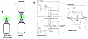
In single particle imaging applications, the number of photons detected from the fluorescent label plays a crucial role in the quantitative analysis of the acquired data. Currently, particle tracking experiments are typically carried out on either an inverted or an upright microscope, in which a single objective lens illuminates the sample and also collects the fluorescence signal from it. Note that although fluorescence emission from the sample occurs in all directions (i.e., above and below the sample), the use of a single objective lens in these microscope configurations results in collecting light from only one side of the sample (see Fig. 4a). Even if a high numerical aperture objective lens is used, not all photons emitted at one side of the sample can be collected due to the finite collection angle of the objective lens. Thus even under the best imaging conditions conventional microscopes collect only a fraction of the photons emitted from the sample.
To address this problem, we have implemented a microscope configuration that uses two opposing objective lenses, where one of the objectives is in an inverted position and the other objective is in an upright position [10]; see Fig. 4b. We refer to this configuration as dual objective multifocal plane microscopy (dMUM).

Figure 4. Dual Objective MUM. Panel (a) shows the light gathering capability of a standard microscope and panel (b) shows the same for dMUM. Panel (c) shows the schematic of dMUM [10]. that is capable of imaging the sample from top and bottom. Our specific implementation of the dMUM imaging configuration used two inverted microscopes (Zeiss AxioObserver), where one of the microscopes (top scope) was in an upside down orientation and mounted on linear translation stages that were then attached to the other microscope (bottom scope).
We have shown that dMUM has higher photon collection efficiency when compared to standard microscope [10]. We have also shown that fluorescent labels can be localized with better accuracy in 2D and 3D when imaged through dMUM than when imaged through a standard microscope [10]. Further, we have compared MUM with dMUM from the point of view of 3D localization and tracking. Our results show that dMUM provides consistently better z-localization accuracy when compared to MUM [10].
Designing the focal plane spacing for MUM
An important question in MUM experiments is how the number of focal planes and their spacings should be chosen to achieve the best possible localization accuracy along the z-axis. To address this problem we have developed the MUMDesignTool. The MUMDesignTool is a new GUI based toolbox, under our previously developed FandPLimitTool, that allows users to calculate the limits on the accuracy with which the 3D location of a single molecules can be estimated when imaged using a MUM setup. The software supports the calculation of these limits along the z-axis for different focal planes in real-time and thereby helps to optimize the design of MUM experiments. The user can calculate limits for a variety of imaging scenarios. The technical details of the methodology used for calculating the accuracy limits for a MUM setup are given in [11] and the software is avilable at MUMDesignTool homepage.
References
[1] Prabhat, P., Ram, S., Ward, E. S. and Ober, R. J. Simultaneous imaging of different focal planes in fluorescence microscopy for the study of cellular dynamics in three dimension.IEEE Transactions on Nanobioscience , 3, 237-242, 2004. Full text ![]() — PubMed
— PubMed ![]() (First report of 3D subcellular tracking with MUM in live cells)
(First report of 3D subcellular tracking with MUM in live cells)
[2] Prabhat, P., Ram, S., Ward, E. S. and Ober, R. J. Simultaneous imaging of several focal planes in fluorescence microscopy for the study of cellular dynamics in 3D. Proceedings of the SPIE, 6090, 115-121, 2006. Full text ![]()
[3] Prabhat, P., Gan, Z., Chao, J., Ram, S., Vaccaro, C., Gibbons, S., Ober, R. J. and Ward, E. S. Elucidation of intracellular recycling pathways leading to exocytosis of the Fc receptor, FcRn, by using multifocal plane microscopy. Proceedings of the National Academy of Sciences, USA, 104, 5889-5894, 2007. Full text ![]() — Supplementary text
— Supplementary text ![]() — PubMed
— PubMed ![]() (First report of 3D single molecule tracking of QD labeled IgGs in live cells)
(First report of 3D single molecule tracking of QD labeled IgGs in live cells)
[4] Ram, S., Ward, E. S., and Ober, R. J. How accurately can a single molecule be localized in three dimensions using a fluorescence microscopy? Proceedings of the SPIE, 5699: 426-435, 2005. Full text ![]() — PubMed
— PubMed ![]() (Reports the quantitative analysis of the poor depth discrimination capability of conventional optical microscopes)
(Reports the quantitative analysis of the poor depth discrimination capability of conventional optical microscopes)
[5] Ram, S., Chao, J., Prabhat, P., Ward, E. S., and Ober, R. J. A novel approach to determining the three-dimensional location of microscopic objects with applications to 3D particle tracking. Proceedings of the SPIE, 6443: 6443-0C, 2007. Full text ![]() (First report to show the superior properties of MUM for z localization of single molecules)
(First report to show the superior properties of MUM for z localization of single molecules)
[6] Ram, S., Prabhat, P., Chao, J., Ward, E. S., and Ober, R. J. High accuracy 3D quantum dot tracking with multifocal plane microscopy for the study of fast intracellular dynamics in live cells. Biophysical Journal, 95, 6025-6043, 2008. Full text ![]() — Supplementary text
— Supplementary text ![]() —PubMed
—PubMed ![]() (Reports the implementation and validation of The MUM localization algorithm MUMLA, and a detailed analysis of depth discrimination problem. The paper also reports 3D single molecule tracking of QD labeled IgGs undergoing endocytosis in live cells)
(Reports the implementation and validation of The MUM localization algorithm MUMLA, and a detailed analysis of depth discrimination problem. The paper also reports 3D single molecule tracking of QD labeled IgGs undergoing endocytosis in live cells)
[7] Chao, J., Ram, S., Abraham, A., Ward, E. S., and Ober, R. J. Resolution in 3D in multifocal plane microscopy. Proceedings of the SPIE, 6861: 68610Q, 2008. Full text ![]() (First report discussing the 3D resolving power of MUM)
(First report discussing the 3D resolving power of MUM)
[8] Chao, J., Ram, S., Ward, E. S., and Ober R. J. 3D resolution measure for multifocal plane microscopy. Proceedings of the IEEE International Symposium on Biomedical Imaging: From Nano to Macro, 1339-1342, 2008. Full text ![]() — PubMed
— PubMed ![]() (Additional results on 3D resolution of MUM)
(Additional results on 3D resolution of MUM)
[9] Chao, J., Ram, S., Abraham, A., Ward, E. S., and Ober, R. J. A resolution measure for three – dimensional microscopy. Optics Communications, 282: 1751-1761, 2009. PubMed![]() (A detailed analysis regarding quantifying the 3D resolution of optical microscopes)
(A detailed analysis regarding quantifying the 3D resolution of optical microscopes)
[10] Ram, S., Prabhat, P., Ward, E. S., and Ober, R. J. Improved single particle localization accuracy with dual objective multifocal plane microscopy. Optics Express, 17, 6881-6898, 2009. Full text ![]() — PubMed
— PubMed ![]() (First report of dual objective MUM imaging configuration)
(First report of dual objective MUM imaging configuration)
[11] Tahmasbi, A., Ram, S., Chao, J., Abraham, A. V., Tang, F. W., Ward, E. S., and Ober, R. J. Designing the focal plane spacing for multifocal plane microscopy. Optics Express, 22(14), 16706-16721, 2014. Full text ![]() — PubMed
— PubMed ![]() — Software
— Software ![]() (First report on designing the plane spacing for a MUM setup)
(First report on designing the plane spacing for a MUM setup)

